Geometry & boundaries
Drawings, CAD, sketches, support conditions, constraints and known simplifications.
Services
Abaqus-based finite element modelling for components, supports, tanks, connections, and industrial assemblies where simplified checks cannot represent the real response.
Buyer problem
Engineering teams often need more than a global design check. Local contact, plasticity, large deformation, buckling, thermal stress, or connection behavior can govern the decision even when the overall structure appears acceptable.
Typical inputs
Drawings, CAD, sketches, support conditions, constraints and known simplifications.
Material grade, available test data, load history, temperature, pressure, blast/VCE or operating assumptions.
What the simulation must answer: local stress, damage indicator, comparison, screening, report or research evidence.
Technical depth
Use this path when a component or assembly is governed by local behavior: contact separation, plastic strain concentration, shell-to-solid transitions, large deformation, support flexibility, local buckling, thermal stress, or load transfer through a connection. It is especially useful when a simplified hand check gives the right order of magnitude but cannot explain where the demand concentrates or why a detail is vulnerable.
Models can be built in Abaqus/Standard or Abaqus/Explicit depending on the physics and stability of the problem. The modelling plan may include shell, solid or mixed discretization, tie/contact strategies, nonlinear material behavior, gravity or preload states, amplitude definitions, output requests, and sensitivity checks around the uncertain variables that actually affect the decision.
Before results are interpreted, Axis FEA reviews units, boundary conditions, contact behavior, reaction-force paths, energy balance, convergence or stable time increment behavior, mesh density in critical regions and history outputs. This is where a contour plot becomes a defensible engineering result rather than a screenshot.
The final value is decision support: identifying critical zones, comparing design or retrofit options, understanding whether the model response is credible, and documenting assumptions clearly enough that another engineer can review the logic.
Typical inputs
Scoping note
The level of modelling is selected after reviewing the engineering question, available data, uncertainty and required decision. Axis does not recommend high-complexity simulation when a simpler verified check is more appropriate.
Related proof
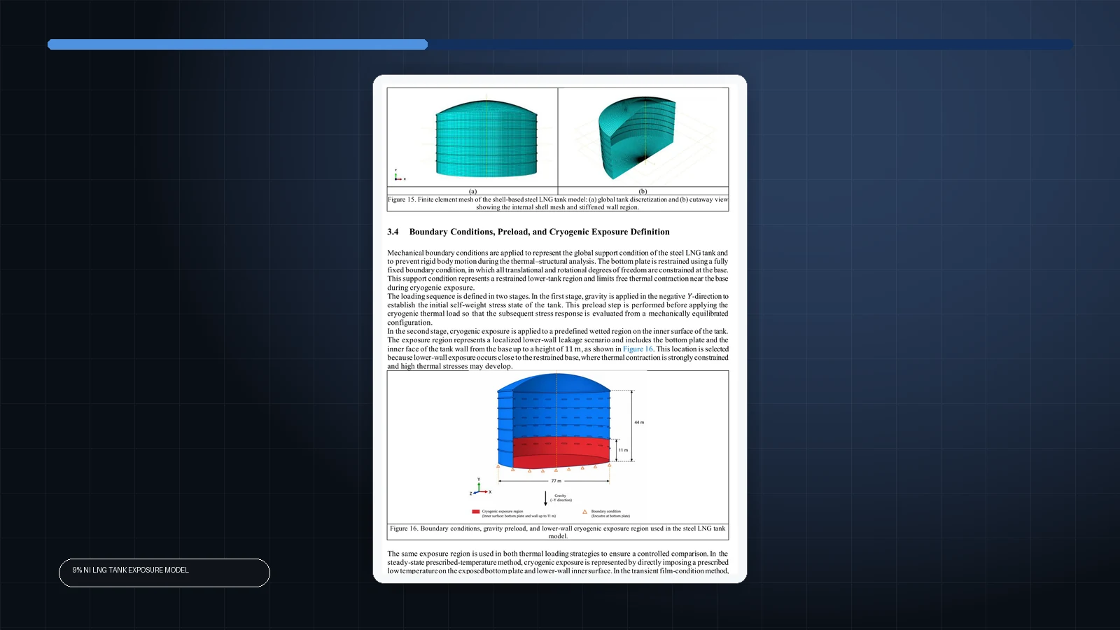
Finite element comparison of prescribed-temperature and transient film-condition thermal loading for cryogenic spill-induced stress in a shell-based 9% Ni steel LNG tank.
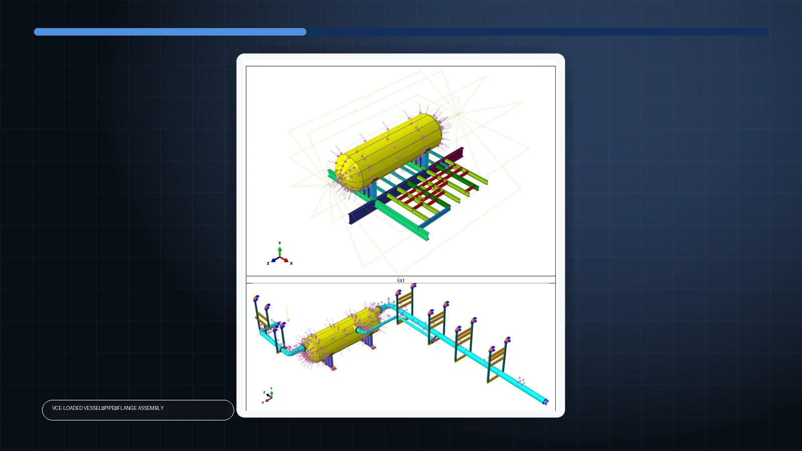
Nonlinear structural–environmental assessment linking VCE-induced local deformation in a connected LNG vessel–pipe–flange system to credible cryogenic-spill initiation regions.
Send available files and the engineering question. Axis FEA will respond with a suitable analysis route and required inputs.